Solutions to Shrinkage in Die Casting Front Covers
On this page
The development of the automobile manufacturing industry has put higher and higher demands on reducing energy consumption. Auto parts have gradually transformed from cast iron parts to aluminum die castings. Products are developing in the direction of lightweight, high integration and high performance, and more and more parts with complex structures and high density requirements have appeared. Die casting production requires that the wall thickness of the parts be as uniform as possible to ensure that the die casting solidifies as much as possible at the same time during cooling. However, when the wall thickness of the parts is very different, internal shrinkage will appear in the thick wall of the casting. In order to eliminate product leakage caused by shrinkage in die castings, partial extrusion technology is generally used to solve casting defects. The engine front cover is a key part of the automobile engine. It is used to seal the engine oil channel transmission. The internal density of the parts is very high, and there must be no leakage in the internal oil pipelines.
1. Overview of the Front Cover
The front cover weighs 3.6 kg and is made from ADC12 alloy. The overall dimensions are 606.2 mm × 351.4 mm × 20 mm, with an average wall thickness of 3 mm. The mold cavity is designed as a single mold with one cavity, and the product has uneven wall thickness. An airtight test is required after processing, with no leakage permitted between the oil channels under 0.3MPa. The casting is a sealed part with uneven wall thickness. The mold structure includes two sets of core-pulling mechanisms, with the slide driven by a cylinder. A single-side feeding method is used, with multi-branch feeding pushed forward in parallel, promoting cavity filling and forming while reducing casting pores. The die-casting machine used is an Idra 22 000 kN, with a casting pressure of 90MPa, a punch diameter of 120 mm, and a gate speed of 60 m/s.

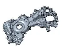
Figure 1 Front cover
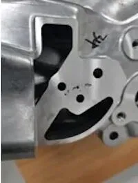
After machining, a leakage test revealed leakage between the two oil channel holes, resulting in a product qualification rate of 20%. The product was sectioned, revealing that a large shrinkage hole between the oil channels was the primary cause of the leakage. The sectioning image is shown in Figure 2.

Figure 2 Product cutaway image

Figure 1 Front cover
After machining, a leakage test revealed leakage between the two oil channel holes, resulting in a product qualification rate of 20%. The product was sectioned, revealing that a large shrinkage hole between the oil channels was the primary cause of the leakage. The sectioning image is shown in Figure 2.

Figure 2 Product cutaway image
2. Defect Analysis and Solutions
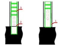
The leakage occurs between the two oil channels on the moving mold side, where the wall thickness is thick and uneven, and the oil channel aperture is relatively small (6 mm), leading to the easy formation of shrinkage holes. A 16 mm oblique core-pulling hole is present on the static mold side opposite the oil channel hole, and the wall thickness between the oil channel holes is relatively large. Modifying the oblique core-pulling hole core changes the core-pulling to core-pulling plus extrusion, which compensates for the shrinkage in the oil channel hole and increases the density between the oil channel holes. Typically, the partial extrusion function aligns with the direction of the moving and static molds, consistent with the die-casting machine's mold opening direction, allowing the extrusion pin to be pulled in and out anytime after the mold is opened. In this project, partial extrusion is directed toward the oblique slider on the side. Before the mold is opened, the extrusion pin must be fully retracted to avoid breaking the casting. If a jam occurs during retraction, the casting may crack if not fully retracted. To prevent the extrusion pin from getting stuck in the pin sleeve during movement and to enhance the core spraying function, the extrusion pin is pushed out from the bottom position when the mold is opened for spraying, with lubrication applied to increase its lubricity. The extrusion pin is then retracted to the bottom position, ready for mold closing and injection. Considering the production risks and core spraying requirements, the partial extrusion utilizes a core-pulling and extrusion structure. After the mold is opened and the casting is removed, the spraying robot controls the extrusion pin cylinder, pushing out the in-position signal, and drives the cylinder during spraying to achieve the core spraying function. After injection extrusion, the die-casting machine controls the extrusion pin cylinder to retract. If the extrusion pin cannot fully retract, the core-pulling signal triggers an alarm to prevent forced mold opening and product cracking. Given the extrusion pin's specific position, its end face aligns with the product's end face when retracted, and the bottom hole of the casting is directly extruded during injection. The specific structural form is illustrated in Figure 3. In this pressurization method, the extrusion pin directly extrudes the casting hole, avoiding contact between the aluminum and the extrusion pin, thus preventing aluminum from entering the extrusion pin sleeve, which could cause jamming or wear. The extrusion pin extends during spraying and receives lubrication from fixed-point spraying, significantly reducing friction between the extrusion pin and the pin sleeve. Additionally, an oil groove on the pin applies grease to ensure local pressurization and continuous production.

(a) Before extrusion (b) After extrusion
Figure 3 Extrusion pin structure
The tolerance clearance between the extrusion pin and the pin sleeve directly impacts production continuity and the extrusion pin's service life. Generally, the larger the tolerance between the extrusion pin and the pin sleeve, the greater the clearance, making it easier for the aluminum to enter and jam the extrusion pin sleeve. The nominal size of the die extrusion pin is 15 mm, with a clearance of 0.05-0.11 mm between the die and the extrusion pin.
3. Production verification
3.1 Extrusion Parameter Debugging
During extrusion production, the delayed extrusion time and holding time are set based on the boost signal. During production debugging, the best external and internal quality is achieved by adjusting different extrusion delays and holding times (Table 1).
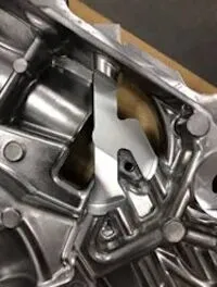
After debugging and verifying various parameter combinations, it was found that the die-casting products produced under the fourth group of parameters exhibited the best appearance quality and the most stable production. The products produced are shown in Figure 4.

Figure 4 Qualified products
Table 1 Extrusion time and holding time setting
| Group 1 | Group 2 | Group 3 | Group 4 | Group 5 | Group 6 | Group 7 | |
| Extrusion delay/s | 1.0 | 1.5 | 2.0 | 2.5 | 3.0 | 3.5 | 3.5 |
| Pressure holding time/s | 2.5 | 2.5 | 3.5 | 3.5 | 3.8 | 3.5 | 3.0 |
After debugging and verifying various parameter combinations, it was found that the die-casting products produced under the fourth group of parameters exhibited the best appearance quality and the most stable production. The products produced are shown in Figure 4.

Figure 4 Qualified products
3.2 Internal Quality and Leakage Tests
The castings produced under the fourth group of parameters did not leak after the processing seal test, and after cutting the castings, no shrinkage holes were found inside the blank (Figure 5), indicating that the extrusion effect was ideal. During the debugging and production process, the extrusion effect of the static mold slider met the expected design specifications. After batch production and sealing verification, the product qualification rate was 99%.

Figure 5 No shrinkage hole in the product after cutting

Figure 5 No shrinkage hole in the product after cutting
4. Conclusion
The combination of core pulling, extrusion, and linkage core insertion spraying technology, driven by the robot spraying signal, successfully realized the partial extrusion function of the inclined slider, greatly improving the internal quality of the casting. As the casting structure becomes increasingly complex, with more uneven wall thicknesses and higher internal density requirements.