Optimizing Zinc Alloy Casting Die-cast Parts
In the manufacturing process of die casting zinc alloys, the filling mode of molten metal is one of the key factors affecting the quality of castings. Many die casting defects such as lacking pouring, cold shut, gas holes, and shrinkage depression are related to the filling mode. At the same time, the filling mode is also one of the key factors affecting the service life of the mold. Therefore, using the simulation software to accurately predict the filling process of the die-cast part can effectively test the rationality of the gating system's design, and optimize the setting of the gate location, the size of the runner and die-cast process parameters. Taking a zinc alloy die casting part as an example, the cloud mold flow service provided by the domestic die-cast simulation software was used to study the influence of different gating systems on the filling state of the die casting part, and solve lacking pouring by optimizing the design form of the gating system.
1. Structural characteristics of castings and pretreatment of the model
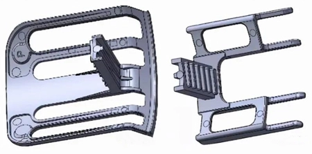
The structure of the zinc alloy die casting is a typical special-shaped structure. The middle convex part is slightly complicated; the structure on both sides is simple, and there is no obvious plane parting surface because of the small size of the casting. A mold with one mold and two cavities is considered. Die-cast part A is designed on the left and B right, so that a set of parts can be produced at the same time. It is also more advantageous from the perspective of production.

Figure 1 The structure of the die-cast part
Combined with the structural characteristics of the die casting part, the partial filling method can be adopted to make the molten metal send to each flow gate as uniformly as possible, ensuring that the molten metal synchronously, quickly and smoothly fills the cavity from the corresponding ingate in each area in the same direction. Set up overflow grooves in the last filling area to ensure the effectiveness of the exhaust. According to the above analysis, the casting system is designed. The total area of the flow gate is about 82.6mm², and the flow gate area of each area is shown in Figure 2.

Figure 2 The original gating system of the die casting part
2. Numerical simulation analysis of the original scheme
Input the designed die casting part into the simulation software. The minimum unit size is 0.25mm, and a total of 8,429,056 cells are generated.
When the mold is filled by 80% to 85%, the filling speeds of the two ribs above and below the left casting are different; finally, two strands of molten metal converge at the corner of the die casting part. The entrapped air cannot be discharged from the mold cavity, because the confluence is far away from the overflow groove. The overall evaluation of this filling scheme shows that after the molten metal enters the cavity, it does not achieve the effect of filling the cavity forward synchronously, which is likely to cause defects such as air entrapment and cold shut in the casting part.
According to experience, the above inconsistency in flow velocity may lead to air entrapment and inclusions. The most likely reason is that the flow gate area at A and D is much smaller than that at B and C, resulting in much greater resistance of molten metal at A and D than that at B and C.
Through the simulation, it can be found that the original design of the gating system of the original scheme did not meet the original intention of the molten metal advancing smoothly and synchronously in the injection process, and the position of the overflow groove did not play its role. Gas entrapment occurred in the inner die casting part at the end.
3. Re-simulation of optimized design
According to the above analysis results, the gating system of the die casting was optimized. Expanded the area of the flow gate at A and D from 3.3mm² to 8.6mm² to reduce the metal liquid resistance in these two places. The optimized gating system is shown in Figure 3.

Figure 3 The optimized gating system of the die casting part
The optimized gating system was input to the simulation software for simulation calculation. After recalculation, it was found that the original inconsistent flow rate has been significantly improved, and the confluence point at the filling end of the molten metal has also moved to the position of the overflow tank, which could effectively discharge the gas from the cavity.
4. Production verification
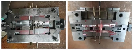
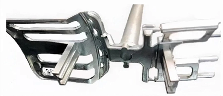
After some simulation analysis and demonstration, the mold design was optimized (Figure 4), and the die-cast production verification was carried out. The die-cast part (Figure 5) has a good shape and a clear outline.

Figure 4 The mold

Figure 5 The zinc alloy die casting part
5. Conclusion
The die-cast simulation analysis predicts the occurrence of die casting defects related to the filling process, which can be effectively improved and controlled before the die casting is produced, and guide the mold designer to optimize the casting system step by step to avoid design mistakes and shorten the time of the trial production and finalization cycle of the zinc alloy die casting. It not only saves time and costs, but also improves the qualification rate of the product.
1. Structural characteristics of castings and pretreatment of the model
The structure of the zinc alloy die casting is a typical special-shaped structure. The middle convex part is slightly complicated; the structure on both sides is simple, and there is no obvious plane parting surface because of the small size of the casting. A mold with one mold and two cavities is considered. Die-cast part A is designed on the left and B right, so that a set of parts can be produced at the same time. It is also more advantageous from the perspective of production.

Figure 1 The structure of the die-cast part
Combined with the structural characteristics of the die casting part, the partial filling method can be adopted to make the molten metal send to each flow gate as uniformly as possible, ensuring that the molten metal synchronously, quickly and smoothly fills the cavity from the corresponding ingate in each area in the same direction. Set up overflow grooves in the last filling area to ensure the effectiveness of the exhaust. According to the above analysis, the casting system is designed. The total area of the flow gate is about 82.6mm², and the flow gate area of each area is shown in Figure 2.

Figure 2 The original gating system of the die casting part
2. Numerical simulation analysis of the original scheme
Input the designed die casting part into the simulation software. The minimum unit size is 0.25mm, and a total of 8,429,056 cells are generated.
When the mold is filled by 80% to 85%, the filling speeds of the two ribs above and below the left casting are different; finally, two strands of molten metal converge at the corner of the die casting part. The entrapped air cannot be discharged from the mold cavity, because the confluence is far away from the overflow groove. The overall evaluation of this filling scheme shows that after the molten metal enters the cavity, it does not achieve the effect of filling the cavity forward synchronously, which is likely to cause defects such as air entrapment and cold shut in the casting part.
According to experience, the above inconsistency in flow velocity may lead to air entrapment and inclusions. The most likely reason is that the flow gate area at A and D is much smaller than that at B and C, resulting in much greater resistance of molten metal at A and D than that at B and C.
Through the simulation, it can be found that the original design of the gating system of the original scheme did not meet the original intention of the molten metal advancing smoothly and synchronously in the injection process, and the position of the overflow groove did not play its role. Gas entrapment occurred in the inner die casting part at the end.
3. Re-simulation of optimized design
According to the above analysis results, the gating system of the die casting was optimized. Expanded the area of the flow gate at A and D from 3.3mm² to 8.6mm² to reduce the metal liquid resistance in these two places. The optimized gating system is shown in Figure 3.

Figure 3 The optimized gating system of the die casting part
The optimized gating system was input to the simulation software for simulation calculation. After recalculation, it was found that the original inconsistent flow rate has been significantly improved, and the confluence point at the filling end of the molten metal has also moved to the position of the overflow tank, which could effectively discharge the gas from the cavity.
4. Production verification
After some simulation analysis and demonstration, the mold design was optimized (Figure 4), and the die-cast production verification was carried out. The die-cast part (Figure 5) has a good shape and a clear outline.

Figure 4 The mold

Figure 5 The zinc alloy die casting part
5. Conclusion
The die-cast simulation analysis predicts the occurrence of die casting defects related to the filling process, which can be effectively improved and controlled before the die casting is produced, and guide the mold designer to optimize the casting system step by step to avoid design mistakes and shorten the time of the trial production and finalization cycle of the zinc alloy die casting. It not only saves time and costs, but also improves the qualification rate of the product.