How to Solve the Problem of Shrinkage Holes of Engine Front Cover Die Casting Parts?
Summary
There are many oil passages in the front cover of the automobile engine and they are independent. The oil passages shall not leak due to penetration caused by shrinkage holes. When designing the die casting mold, aiming at the parts with relatively high requirements for the internal compactness of each oil channel, partial extrusion is realized by core-pulling and extrusion, and extrusion alarm and insert spraying are provided in the die casting machine to complete partial extrusion and the coordination of the opening and closing of molds, reducing the internal shrinkage hole of the die casting part, improving its compactness, and meeting the testing sealing requirements for the front cover.
With the development of the automobile manufacturing industry, the requirements for reducing energy consumption are becoming higher and higher. Automobile parts are gradually transformed from iron castings to aluminum die castings. Products are developing in the direction of lightweights, high integration and good performance, and more and more parts with complex structure and high compactness requirements appear.
The die casting part is required to have uniform thickness as much as possible in the manufacturing process to ensure that the die casting part is solidified as far as possible. However, when the wall thickness of the parts differs greatly, the internal shrinkage hole will appear at the thick wall of the die casting. In order to eliminate the leakage caused by shrinkage holes in die castings, partial extrusion technology is generally used to solve the problem. The front cover of the engine is a key part of the automobile engine. It is used to seal the transmission of the engine oil passage. The requirement for the internal compactness of the parts is very high. The internal oil pipelines must not leak and their oil must not mix with each other.
The spraying function of core-pulling combined with linkage core spraying is adopted to solve the problem of oil leakage in the oil passage caused by shrinkage holes in the actual production of engine front cover parts.
1. The technical requirements and structural analysis of the product
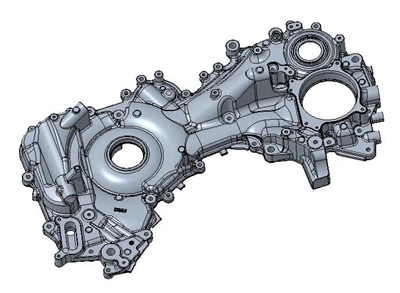
The weight of the front cover is 3.6 kg and it is made from ADC12 alloys. Its external dimension is 606.2 × 351.4 × 20 mm. Its average wall thickness is 3 mm. Its mold cavity is one mold and one cavity, and the product's wall thickness is uneven. An airtight test is required after processing, and no leakage between the lower oil passages with pressure of 0.3MPa is allowed.

Figure 1 The front cover

Figure 1 The front cover
2. The structural design of the gating system and mold
The die casting part belongs to a sealed part with uneven wall thickness. The mold structure is designed with 2 sets of core pulls. A hydraulic cylinder slider is adopted. The single-sided feeding method is divided into multiple feeding and feeding in parallel. It is conducive to the filling and forming of the cavity and reduces gas holes of the die casting part. The Idra die casting machine of 22000kN is adopted. Its casting pressure is 90MPa, punch diameter 120mm, and the flow gate's speed 60 m/s.
3. Internal quality of die castings after processing
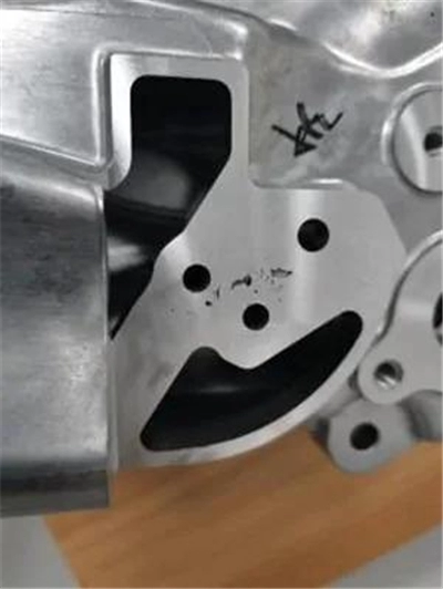
After machining, a leak test was carried out, and it was found that there was a leak between the two oil passage holes. The product's qualification rate was 20%. The product was sectioned and it was found that the large shrinkage cavity between the oil passages was the main cause of the leakage. The sectioned picture is shown in Figure 2.

Figure 2 The sectioned part
4. The determination of the partial extrusion plan
4.1 The analysis of the extrusion position
Because the leakage position is between the two oil passages on the movable mold side, and the wall thickness at this position is thick and uneven; the diameter of the oil passage is relatively small (Φ6 mm), and shrinkage holes are easy to occur inside. There is an oblique core-pulling hole of Φ16 mm on the side of the static mold opposite the oil passage hole. The wall thickness between the oil passage hole and oblique core-pulling hole is relatively great. The mold core of the oblique core pulling hole is changed; the core pulling is replaced with core pulling and extrusion, which can greatly feed the internal part with shrinkage holes and increase the compactness of the oil passage holes.
4.2 The design of extrusion
Usually, the partial extrusion function is distributed in the direction of the moving and static molds, which is the same as the mold's opening direction of the die casting machine. The extrusion pin is inserted and removed at any time after the mold is opened. The partial extrusion is located in the direction of the side oblique slider. The extrusion pin must be completely retracted and away from the die casting part before the machine tool opens the mold. Otherwise, the extrusion pin will break the die casting part after the mold is opened. If there is slow retraction or incomplete retraction in the production process, the die casting part will crack. In order to prevent the extruded pin from jamming with the pin sleeve in the movement process, the spraying function of the insert core is provided. When the mold is sprayed, the extruded pin needs to be ejected from the bottom position again to receive spray lubrication and increase the lubricity of the extruded pin. Subsequently, the extruded pin is returned to the bottom again to wait for the closing of the mold and injection. The core pulling and extrusion structure is adopted for the partial extrusion based on the above manufacturing risks and the requirements for the spraying function of the insert core. After the mold is opened and the die casting part is taken out, the spraying robot controls the extrusion pin cylinder to eject in place; the cylinder is driven to eject during spraying, realizing the spraying of the insert core. After the injection and extrusion, the extrusion pin cylinder is controlled by the die casting machine to retract. If the extrusion pin cannot be retracted well, the machine tool's loose core will sound an alarm to prevent forced mold opening and cracking of the product.
4.3 The schematic diagram of partial extrusion
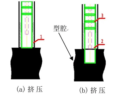
Because of the particularity of the position of the extrusion pin, its end face is flush with the end face of the product when it is retracted, and the bottom hole of the die casting part is directly extruded during the injection. The specific structure is shown in Figure 3. This pressing method is the extrusion pin directly extruding the die casting part's hole, avoiding the contact between the aluminum liquid and the extrusion pin, and jamming or wear caused by the aluminum liquid entering the extrusion pin sleeve won't happen. The squeeze pin extends during spraying, which is lubricated by fixed-point spraying and greatly reduces the friction between the squeeze pin and pin sleeve. In addition, grease grooves are applied on the pins to ensure continuous production under partial pressure increase.
4.4 Extrusion pin and pin sleeve clearance control
The Tolerance fit clearance between the extrusion pin and pin sleeve directly affects the production continuity and service life of the extrusion pin. Under normal circumstances, the greater the fit tolerance between the extrusion pin and the pin sleeve is, the greater the gap becomes, and the extrusion pin sleeve is likely to get stuck when getting into the molten aluminum. The nominal size of the mold's extrusion pin is φ15 mm, and the gap between extrusion pins is from 0.05 to 0.11 mm.

Figure 3 The structure of the extrusion pin
5. Verification
5.1 Adjustment of extrusion parameters
Set the delayed extrusion time and dwell time according to the pressure increase signal in the extrusion process, and verify the best external and internal quality by setting different extrusion delay and dwell time during adjustment. See Table 1.
Table 1 Setting of extrusion time and dwell time
3. Internal quality of die castings after processing
After machining, a leak test was carried out, and it was found that there was a leak between the two oil passage holes. The product's qualification rate was 20%. The product was sectioned and it was found that the large shrinkage cavity between the oil passages was the main cause of the leakage. The sectioned picture is shown in Figure 2.

Figure 2 The sectioned part
4. The determination of the partial extrusion plan
4.1 The analysis of the extrusion position
Because the leakage position is between the two oil passages on the movable mold side, and the wall thickness at this position is thick and uneven; the diameter of the oil passage is relatively small (Φ6 mm), and shrinkage holes are easy to occur inside. There is an oblique core-pulling hole of Φ16 mm on the side of the static mold opposite the oil passage hole. The wall thickness between the oil passage hole and oblique core-pulling hole is relatively great. The mold core of the oblique core pulling hole is changed; the core pulling is replaced with core pulling and extrusion, which can greatly feed the internal part with shrinkage holes and increase the compactness of the oil passage holes.
4.2 The design of extrusion
Usually, the partial extrusion function is distributed in the direction of the moving and static molds, which is the same as the mold's opening direction of the die casting machine. The extrusion pin is inserted and removed at any time after the mold is opened. The partial extrusion is located in the direction of the side oblique slider. The extrusion pin must be completely retracted and away from the die casting part before the machine tool opens the mold. Otherwise, the extrusion pin will break the die casting part after the mold is opened. If there is slow retraction or incomplete retraction in the production process, the die casting part will crack. In order to prevent the extruded pin from jamming with the pin sleeve in the movement process, the spraying function of the insert core is provided. When the mold is sprayed, the extruded pin needs to be ejected from the bottom position again to receive spray lubrication and increase the lubricity of the extruded pin. Subsequently, the extruded pin is returned to the bottom again to wait for the closing of the mold and injection. The core pulling and extrusion structure is adopted for the partial extrusion based on the above manufacturing risks and the requirements for the spraying function of the insert core. After the mold is opened and the die casting part is taken out, the spraying robot controls the extrusion pin cylinder to eject in place; the cylinder is driven to eject during spraying, realizing the spraying of the insert core. After the injection and extrusion, the extrusion pin cylinder is controlled by the die casting machine to retract. If the extrusion pin cannot be retracted well, the machine tool's loose core will sound an alarm to prevent forced mold opening and cracking of the product.
4.3 The schematic diagram of partial extrusion
Because of the particularity of the position of the extrusion pin, its end face is flush with the end face of the product when it is retracted, and the bottom hole of the die casting part is directly extruded during the injection. The specific structure is shown in Figure 3. This pressing method is the extrusion pin directly extruding the die casting part's hole, avoiding the contact between the aluminum liquid and the extrusion pin, and jamming or wear caused by the aluminum liquid entering the extrusion pin sleeve won't happen. The squeeze pin extends during spraying, which is lubricated by fixed-point spraying and greatly reduces the friction between the squeeze pin and pin sleeve. In addition, grease grooves are applied on the pins to ensure continuous production under partial pressure increase.
4.4 Extrusion pin and pin sleeve clearance control
The Tolerance fit clearance between the extrusion pin and pin sleeve directly affects the production continuity and service life of the extrusion pin. Under normal circumstances, the greater the fit tolerance between the extrusion pin and the pin sleeve is, the greater the gap becomes, and the extrusion pin sleeve is likely to get stuck when getting into the molten aluminum. The nominal size of the mold's extrusion pin is φ15 mm, and the gap between extrusion pins is from 0.05 to 0.11 mm.

Figure 3 The structure of the extrusion pin
5. Verification
5.1 Adjustment of extrusion parameters
Set the delayed extrusion time and dwell time according to the pressure increase signal in the extrusion process, and verify the best external and internal quality by setting different extrusion delay and dwell time during adjustment. See Table 1.
Table 1 Setting of extrusion time and dwell time
| Group 1 | Group 2 | Group 3 | Group 4 | Group 5 | Group 6 | Group 7 | |
| Extrusion time | 1.0 | 1.5 | 2.0 | 2.5 | 3.0 | 3.5 | 3.5 |
| Dwell time | 2.5 | 2.5 | 3.5 | 3.5 | 3.8 | 3.5 | 3.0 |
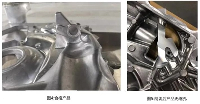
After debugging and verification of different combined parameters, it is found that the die casting product under parameters of group 4 has the best appearance quality and the most stable production. The products produced are shown in Figure 4.
5.2 Internal quality and the leak test
The die castings produced by parameters of group 4 have been processed and tested without leakage. After the die castings were cut, there were no shrinkage holes in the die castings (Figure 5); the extrusion effect is ideal.

In the process of debugging and production, the extrusion effect of the static mold slider meets the expected design purpose. After mass production and verification for sealing, the qualification rate of the product is 99%.
6. Conclusion
The core-pulling and extrusion combined with linkage insert core spraying technology, coupled with the robot spraying signal drive realizes the partial extrusion function of the inclined slider and greatly improves the internal quality of the die casting. As the structure of die castings becomes more and more complex and the wall thickness uneven, the requirements for internal compactness are getting higher and higher.