Hot Isostatic Pressing on Gas Holes in Aluminum Alloy Castings (Part One)
Abstract
The study investigated the effect of hot isostatic pressing on gas holes in ZL205A alloy. The results indicate that hot isostatic pressing will flatten the gas holes. However, due to the presence of an oxide film, complete diffusion of each element across the interface does not occur, preventing metallurgical bonding. After hot isostatic pressing and heat treatment, the original gas holes become linear.
Hot Isostatic Pressing (HIP) is a process that utilizes high-pressure gas to uniformly apply external force to castings during heating, eliminating specific holes, increasing casting density, and thereby enhancing mechanical properties. Currently, it is primarily employed in the preparation and development of nuclear materials, aerospace materials, cemented carbide, high-temperature alloys and ceramics, as well as in the development and application of densification processing or defect repair for high-temperature alloys, titanium alloys, aluminum alloys and other components. Currently, there are studies on the impact of the hot isostatic pressing process on the mechanical properties and fatigue properties of aluminum alloy castings. However, there is limited research on the elimination of diverse defects in aluminum alloy castings. This article studies the effect of hot isostatic pressing on holes in ZL205A alloy, aiming to offer guidance for relevant technical personnel.
1. Test processes
To understand the effect of hot isostatic pressing on the gas holes of the ZL205A alloy, a simulation test was designed. The composition of the ZL205A alloy is shown in Table 1, and Table 2 indicates the hot isostatic pressing process parameters. To avoid overburning, the hot pressing temperature cannot exceed the solid solution temperature of the ZL205A alloy (538℃). Taking into account factors such as the temperature deviation of the hot pressing furnace, a temperature of 510 to 530℃ is chosen; the strength of the ZL205A alloy at the hot pressing temperature should not be higher than 100MPa, so the hot pressing pressure is set to 120MPa, and the pressure holding time is 2 hours. The gas medium in the hot pressure treatment furnace is argon.
Table 1 The Chemical composition of ZL205A alloy WB/%
Table 1 The Chemical composition of ZL205A alloy WB/%
| main elements | Impurity elements | ||||||||||
| Cu | Mn | Ti | Cd | V | Zr | B | Al | Fe | Si | Mg | Other elements |
| 4.6 to 5.3 | 0.3 to 0.5 | 0.15 to 0.35 | 0.15 to 0.25 | 0.05 to 0.3 | 0.05 to 0.2 | 0.005 to 0.06 | The rest | Less than and equal to 0.15 | Less than and equal to 0.06 | Less than and equal to 0.05 | Less than and equal to 0.3 |
Table 2 Hot isostatic pressing process parameters
| Temperature/°C | Pressure/MPa | Holding time/h |
| 510 to 530 | 120 | 2 |
1.1 Sample preparation
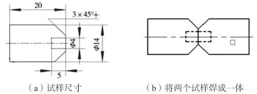
Utilize the ZL205A metal type test bar to process a sample of 14 mm × 20 mm, and drill a small hole of 4 mm × 5 mm in the center of the sample. Process a groove with an angle of 45° on the periphery, with a total of 6 holes. After processing, two samples are butt welded together using body welding wire and the argon arc welding. The size of the processed sample is shown in Figure 1. A closed hole is formed in the middle, similar to the gas hole in the casting, with a total of 3 samples.
(a) The sample’s size (b) Welding the two specimens into one
Figure 1 The schematic diagram of preparation of simulated gas holes
1.2 Test processes
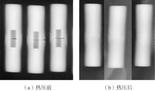
The welded samples were subjected to X-ray inspection, and the inspection results are shown in Figure 2a. Then, the sample was subjected to hot isostatic pressing, and X-ray inspection was performed again after hot pressing. The inspection results are shown in Figure 2b. It can be seen that after hot isostatic pressing, no gas holes were found in the X-ray results. Then, the sample was heat treated. The heat treatment is shown in Table 3. After heat treatment, X-ray inspection was performed again. The inspection results are shown in Figure 3. It was found that a Y-shaped linear defect appeared at the original location where gas holes were present, and cracks appeared on the butt surface of the sample.
Table 3 Heat treatment processes
| Processes | Solid solution and aging temperature/°C | Time/h | Cooling temperatures/°C | Cooling media |
| Solution treatment | 533 to 543 | 10 | 45 to 55 | Air |
| Artificial aging | 170 to 180 | 5 |
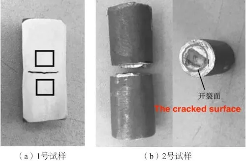
Cut sample No. 1 in Figure 3 from the middle along the axial direction and observe the metallographic structure of the Y-shaped linear defect (square frame area in Figure 4). Cut sample No. 2 along the transverse cracking surface and observe the surface morphology and chemical composition of the cracked joint surface.
(a) Before hot pressing (b) After hot pressing
Figure 2: X-ray inspection results of the sample before and after hot pressing
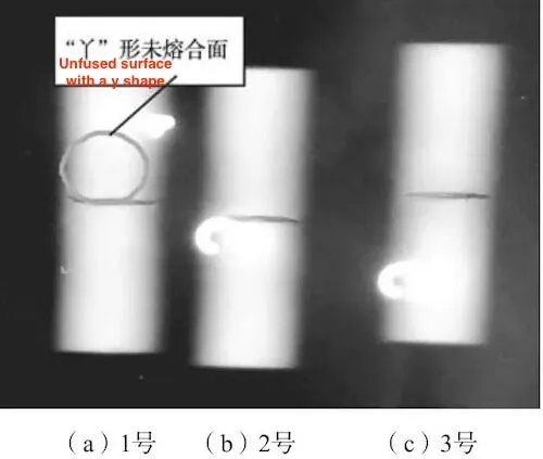
Figure 2: X-ray inspection results of the sample before and after hot pressing

(a) No. 1 (b) No. 2 (c) No. 3
Figure 3: X-ray inspection results of the samples after hot pressing and heat treatment

(a) No. 1 sample (b) No. 2 sample
Figure 4: The schematic diagram of the analysis sample
Observe the metallographic structure of sample No. 1. Check Figure 5 for details. It can be seen that there is indeed an unfused area. Although hot isostatic pressing can bridge the gas holes to a certain extent, a complete metallurgical bonding can not be obtained.
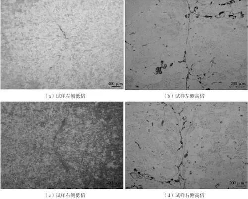
(a) Low magnification on the left side of the sample
(b) High magnification on the left side of the sample
(c) Low magnification on the right side of the sample
(d) High magnification on the right side of the sample
Figure 5: Metallographic structure diagram of the sample No. 1
An electron microscope was used to observe the surface morphology of the cracked surface of sample No. 2 (Figure 6), and an electron probe was utilized to detect the surface’s chemical composition (Figure 7). Judging from the surface morphology of the cracking surface, the surface layer has a typical oxide structure. Judging from the chemical composition of the surface, besides normal alloy elements, it contains a certain proportion of oxygen.
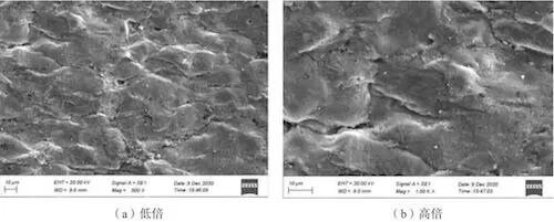
(a) Low magnification (b) High magnification
Figure 6: The surface morphology of cracked surfaces of sample No. 2
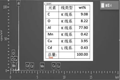
Figure 7: The chemical composition of the cracked surface
Observe the metallographic structure of sample No. 1. Check Figure 5 for details. It can be seen that there is indeed an unfused area. Although hot isostatic pressing can bridge the gas holes to a certain extent, a complete metallurgical bonding can not be obtained.

(a) Low magnification on the left side of the sample
(b) High magnification on the left side of the sample
(c) Low magnification on the right side of the sample
(d) High magnification on the right side of the sample
Figure 5: Metallographic structure diagram of the sample No. 1
An electron microscope was used to observe the surface morphology of the cracked surface of sample No. 2 (Figure 6), and an electron probe was utilized to detect the surface’s chemical composition (Figure 7). Judging from the surface morphology of the cracking surface, the surface layer has a typical oxide structure. Judging from the chemical composition of the surface, besides normal alloy elements, it contains a certain proportion of oxygen.

(a) Low magnification (b) High magnification
Figure 6: The surface morphology of cracked surfaces of sample No. 2

Figure 7: The chemical composition of the cracked surface