SERES Automobile has unveiled the M9 SUV, featuring an integrated die-cast all-aluminum chassis designed to reduce unsprung mass and improve handling performance. Despite advancements, achieving dimensional accuracy in large-scale die-cast parts remains a key challenge for the industry. This paper introduces a control strategy to optimize the die-casting process through the application of heat-treatment-free materials, advanced tooling design, real-time process monitoring, and precise press parameter adjustments. These innovations not only enhance the manufacturing capabilities of new energy vehicles but also offer valuable insights for advancing die-casting technologies.
Streamlined Manufacturing Process for Integrated Die-Cast Rear Bodies
The production of an integrated die-cast rear body involves several precise and interdependent steps, ranging from initial blank die-casting to component assembly and final product testing. Die-casting, the cornerstone of this process, involves injecting molten metal into molds under high pressure to achieve the required shapes. The preparation of molds is critical, as their precision and quality directly influence the outcome. Production adheres to product design specifications and incorporates precision machining techniques. Blank die-casting begins with calibrating machine parameters, such as pressure, speed, and temperature, to align with specific production needs. During this stage, the die-casting machine injects molten metal at high pressure, ensuring complete cavity filling, as illustrated in Figure 2.
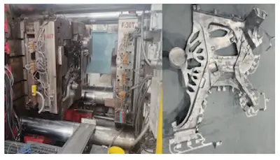
Figure 2 Blank Die Casting
Excess material and burrs on blank castings are removed through cutting and polishing to refine the initial form. The next stage, blank correction, adjusts the casting to ensure compliance with dimensional and shape requirements outlined in the product design, as depicted in Figure 3. Advanced blue light scanning is subsequently employed to capture three-dimensional data, enabling precise comparisons against design specifications. This method significantly enhances defect detection efficiency, identifying even sub-microscopic flaws that would otherwise escape visual inspection. By addressing these issues early, the process ensures the dimensional stability and mechanical reliability of the final product, as shown in Figure 4. As technological advancements and process optimization continue, integrated die-casting is set to play a transformative role in automotive manufacturing, particularly in achieving higher precision and production efficiency.
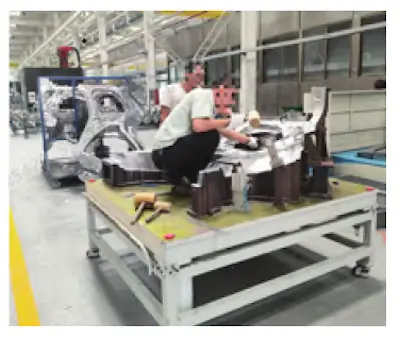
Figure 3 Blank Profiling
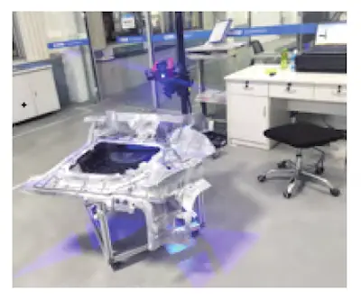
Figure 4 Blue Light Scanning
Dimensional Accuracy Control Scheme
(1) Material Selection
To minimize deformation in large castings following heat treatment, the development and application of heat-treatment-free materials have become a key focus. Research on automotive structural components primarily centers on Al-Si and Al-Mg aluminum alloys, which achieve fine-grain structures through the addition of alloying elements and optimized die-casting processes. This microstructure not only enhances dimensional stability but also delivers mechanical properties on par with traditional heat-treated materials. Notable alloys such as C611 (developed by Alcoa) and SF36 (produced by Rheinmetall, Germany) are extensively employed in manufacturing critical automotive components, including NIO CD pillars and Audi A8 body structures. These materials exhibit superior elongation and robustness under controlled processing conditions, making them ideal for various structural applications. The chemical compositions and mechanical properties of C611 and SF36 are detailed in Tables 1 and 2.
(2) Profiling Tooling Equipment
Positioning Datum
Figure 5 illustrates the positioning scheme for the profiling tooling. Datum points A1 to A4 are used to constrain three degrees of freedom: movement along the Z axis and rotations about the X and Y axes. Hole B serves as the primary positioning feature, constraining two degrees of freedom: movement along the X and Y axes. Hole C is designated as the secondary positioning feature, constraining rotation about the Y axis.
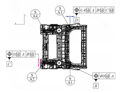
Figure 5 GD&T Drawing of Integrated Rear Body
Profiling Tooling
The trimming die, a specialized stamping tool, removes excess material during the trimming process to achieve precise dimensional targets, including height, diameter, and contour. Its primary function is to trim and refine the edges of formed parts, ensuring smooth, flat end faces and dimensional accuracy essential for subsequent assembly, as depicted in Figure 6.
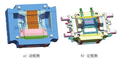
a) Moving die side b) Fixed die side
Figure 6 Die-casting die
The part is mounted on the profiling fixture using RPS (Referenced Point System) points, enabling calibration of its shape, size, and position to meet specified tolerances. This ensures compliance with dimensional accuracy requirements critical for consistent and reliable assembly.
Table 1 Mass fraction of each element in die-cast aluminum alloy
|
Alloy Grade |
Si (%) |
Fe (%) |
Cu (%) |
Mn (%) |
Mg (%) |
Zn (%) |
Ti (%) |
Sr (%) |
Al (%) |
|
C611 |
2.0 - 7.0 |
0.15 - 0.2 |
|
0.4 - 0.8 |
0.15 - 0.25 |
|
0.1 |
0.01 - 0.015 |
Others |
|
SF36 |
9.5 - 11.5 |
≤0.15 |
<0.03 |
0.5 - 0.8 |
0.1 - 0.5 |
≤0.07 |
≤0.15 |
0.01 - 0.03 |
Others |
Table 2 Requirements for tensile mechanical properties of die-cast aluminum alloys
|
Alloy Grade |
Yield Strength (MPa) |
Tensile Strength (MPa) |
Elongation After Fracture A50 (%) |
Average Bending Angle (°) |
|
C611 |
105 |
220 |
10 |
≥45 |
|
SF36 |
120 |
180 |
10 |
≥60 |
(3) Process Control
Blue Light Scanning: it is employed to inspect and measure the blank at critical production stages, including post-profiling, surface and hole machining, and final product profiling. The scanning data is analyzed to detect and address dimensional deviations early in the process. As illustrated in Figure 7, green areas represent dimensions within a tolerance of ±0.5mm, while red and blue areas indicate deviations of ±2mm. Notable discrepancies are observed in the wheel arch regions on both sides and in the overlap area between the front section and the door sill beams.
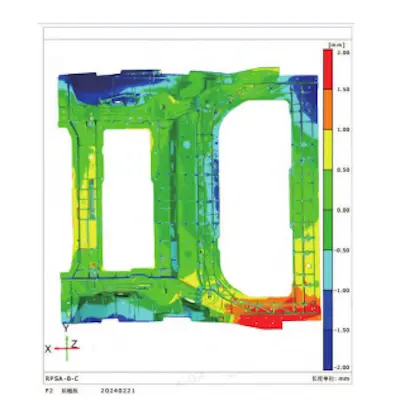
Figure 7 Finished product profiling scanning results
Finished Product Inspection: Fixture Measurement
Inspection fixtures serve as the final quality control step, ensuring all parts meet dimensional accuracy standards prior to delivery. To optimize efficiency and minimize workload, critical measurement points are selected for key components. A measurement record table, exemplified in Figure 8, supports systematic monitoring and documentation of dimensional accuracy, enabling precise evaluation of production quality.
(4) Press Parameter Calibration
Proper calibration of press parameters is essential for achieving consistent quality in die-casting processes.
- Pressure: Injection pressure is maintained between 30 and 90 MPa, while boost pressure ranges from 50 to 300 MPa to ensure complete cavity filling and material consolidation.
- Speed: Low-speed stages operate at 0.1 to 0.5 m/s for initial metal flow, transitioning to 3 to 6 m/s during the high-speed stage. During gate injection, speeds reach 30 to 60 m/s to fill complex geometries.
- Time: Filling time is determined by factors such as casting volume, average wall thickness, and filling speed. Thin-walled components require filling times of less than 0.1 seconds. Holding time varies between 1 to 2 seconds for thin-walled parts and 3 to 5 seconds for thicker components. Cooling time is influenced by product dimensions, structural design, and process temperature.
- Temperature: Pouring temperature, monitored as molten metal temperature in the furnace, ranges from 700 to 740°C. Mold preheating temperatures are set between 150 and 180°C, with continuous operation temperatures maintained at 180 to 220°C.
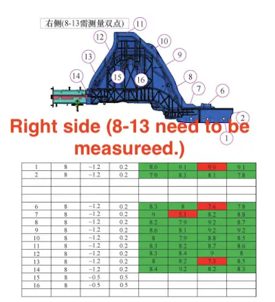
Figure 8 Key measurement point detection process card
Comparative Analysis of Pre- and Post-Improvement
The optimization of material selection, tooling design, process control, and press parameter calibration has significantly enhanced the dimensional accuracy and quality of die-cast components. A statistical analysis of measurement points 6 to 14 on the integrated rear body, conducted using Minitab software, reveals notable improvements. Key results, summarized in Tables 3 to 5, demonstrate reduced dimensional variation and enhanced process stability. Figure 8 illustrates the detection and evaluation of critical measurement points, which were instrumental in identifying and correcting discrepancies during production.
Table 3 Descriptive statistics
|
Sample |
N |
Mean |
Standard Deviation |
Error |
|
Before rectification |
9 |
9.52 |
1.83 |
0.61 |
|
After rectification |
9 |
8.30 |
0.13 |
0.04 |
Table 4 Estimated value of the difference
|
Difference |
Combined Standard Deviation |
95% Lower Limit of the Difference |
|
1.22 |
1.30 |
0.15 |
Statistical Analysis of Rectification Impact
The analysis compares the population means before and after rectification (denoted as μ₁ and μ₂, respectively), under the assumption of equal variance. The difference between the pre- and post-rectification means (μ₁ - μ₂) is used to evaluate the impact of the improvements.
The hypotheses tested were:
- Null hypothesis (H₀): μ₁ − μ₂ = 0 (no improvement)
- Alternative hypothesis (H₁): μ₁ − μ₂ > 0 (significant improvement)
Results show that the lower limit of the difference is 0.153, exceeding the assumed value of 0. The p-value of 0.032, which is below the 0.05 significance threshold, provides sufficient evidence to reject the null hypothesis. This confirms that the rectification measures have led to statistically significant improvements in dimensional accuracy.
These findings highlight that optimal material selection, combined with refined tooling, enhanced process control, and precise press parameter calibration, can substantially enhance the dimensional consistency and quality of die-cast components.
Table 5 Test value
|
T value |
Degree of Freedom |
|
2.00 |
160.03 |
Conclusion
The use of small and medium-sized one-piece die-cast structural components in automotive manufacturing is well-established, but the production of large one-piece die-cast bodies continues to present significant challenges. Overcoming these challenges requires close collaboration between body design and process engineering teams. From a manufacturing technology perspective, current die-cast equipment and molds can support the production of castings with a projected area of up to 20,000 cm². Materials like C611 and SF36, which do not require heat treatment, have demonstrated excellent performance in automotive structural components. The dimensional accuracy control strategy outlined in this paper, which includes optimizing tooling positioning, designing tooling, controlling processes, and calibrating press parameters, has significantly improved the quality and consistency of die-cast components. These advancements not only demonstrate the feasibility of the proposed technology but also establish a solid foundation for scaling up applications in the future.