Cryogenic Treatment Test Results of Die-cast Parts
2.1 Effect of cryogenic treatment on mechanical properties
Figure 3 shows the mechanical properties of die-cast aluminum-silicon alloys subjected to different cryogenic treatments. When cast, the alloy has a tensile strength of 184.8MPa, elongation 6.35%, and hardness HV 90.3. Cryogenic treatment can effectively improve the mechanical properties of die-cast aluminum-silicon alloys. After cryogenic treatment for different times, the mechanical properties of the alloy first increase and then decrease. When the cryogenic treatment time is 12 hours, the mechanical properties of the alloy are maximized, with a tensile strength of 213.2MPa, elongation 8.65%, and hardness HV106.6. Compared with the properties of the as-cast alloy, the tensile strength increased by 15.4%, elongation 36.2%, and hardness 18.1%. By continuing to extend the cryogenic treatment time, although the improvement in the mechanical properties of the alloy gradually decreases, it is still higher than the mechanical properties of the cast aluminum-silicon alloy. When the cryogenic treatment time is 48 hours, the tensile strength of the alloy is 200.6MPa, elongation 7.5%, and hardness HV97.4, which is already lower than the mechanical properties of the alloy after cryogenic treatment for 6 hours. From the perspective of energy conservation, environmental protection and production efficiency, it is of little significance to continue to increase the cryogenic treatment time to improve the mechanical properties of die-cast aluminum-silicon alloys.
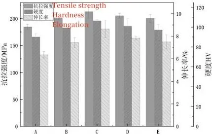
Figure 3 Mechanical properties of die-cast aluminum-silicon alloys treated by different cryogenic treatment processes
2.2 Effect of cryogenic treatment on α-Al phase
Figure 4 shows the morphology of the α-Al phase of die-cast aluminum-silicon alloy treated by different cryogenic treatment processes. For the as-cast die-cast aluminum-silicon alloy, as shown in Figure 4a, the α-Al phase is relatively coarse and has more columnar crystals. The average particle size measured using Image-Pro Plus analysis was 27.22μm. Figure 4b shows the structure after cryogenic treatment for 6 hours. The α-Al phase has been refined and the coarse columnar crystals have been reduced. However, there is still some agglomeration, and the average particle size is 24.42μm. As the cryogenic time increases, the α-Al phase is further refined. When the cryogenic time is 12 hours, the α-Al phase is the smallest, with an average particle size of 22.41μm. Continuing to increase the cryogenic time, the average particle size of α-Al phase increases slightly, but its size is still lower than that of the as-cast alloy compared with the cryogenic sample treated for 12 hours. In short, cryogenic treatment can refine the grains, reduce the agglomeration of columnar crystals and α-Al phases, and promote a more uniform distribution of the organizational structure.
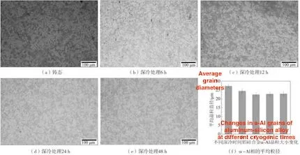
(a) The cast state (b) Cryogenic treatment for 6 hours (c) Cryogenic treatment for 12 hours
(d) Cryogenic treatment for 24 hours (e) Cryogenic treatment for 48 hours (f) Average particle sizes of a-Al phase
Figure 4 Microstructure morphology of α-Al phase of die-cast aluminum-silicon alloy treated by different cryogenic treatment processes
2.3 Effect of cryogenic treatment on eutectic Si phase
Figure 5 shows the morphology of the eutectic Si phase of die-cast aluminum-silicon alloy treated by different cryogenic treatment processes. The eutectic Si phase of the cast alloy is mostly in the form of flakes or strips, as shown in Figure 5a. After cryogenic treatment, the eutectic Si phase begins to become shorter and finer, transforming into a granular form. When the cryogenic time is 12 hours, the eutectic Si phase is significantly refined and tends to be round, as shown by the arrow in Figure 5c. Continuing to increase the cryogenic time, the eutectic Si phase begins to grow slowly again, as shown in Figure 5d and e.
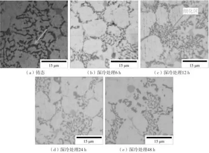
(a) In a cast state (b) Cryogenic treatment for 6 hours (c) Cryogenic treatment for 12 hours
(d) Cryogenic treatment for 24 hours (e) Cryogenic treatment for 48 hours
Figure 5 Microstructure of eutectic Si phase of die-cast aluminum-silicon alloy treated by different cryogenic treatment processes
2.4 Effect of cryogenic treatment on iron-containing phase
Figure 6 shows the morphology of the iron-containing phase of die-cast aluminum-silicon alloy in the as-cast state and cryogenically cooled for 12 hours. The as-cast alloy contains a polygonal block AlFeMnSi phase and a long needle-shaped Al5FeSi phase, as shown in Figure 6a. After cryogenic treatment, the Al5FeSi phase shrinks and becomes passivated, and its outline becomes smooth. The sharp-edged AlFeMnSi phase also tends to be rounded, as shown by the arrow in Figure 6b. After cryogenic treatment, the size of the iron-containing phase in the die-cast aluminum-silicon alloy becomes smaller and its morphology changes, which greatly reduces the effect of splitting on the aluminum matrix.
3. Analysis and discussion
The volume of aluminum-silicon alloy shrinks treated by cryogenic treatment, which causes microscopic stress inside the material and promotes plastic deformation of the material. Figure 7 is a schematic diagram of the refinement process of the tissue produced by the cryogenic process. Before cryogenic treatment, dislocations in the alloy are scattered and have a low density, as shown in Figure 7a; at the beginning of cryogenic treatment, as shown in Figure 7b, the microscopic stress is small, and dislocations inside the grains will gather partially and form dislocations. As the cryogenic treatment proceeds, the stress accumulation increases, and the dislocations gather and become small-angle grain boundaries, which refines the grains, as shown in Figure 7c; the solubility of Si, Fe and other solute atoms in the alloy in the aluminum matrix decreases, and the solute atoms will segregate at dense dislocations near the grain boundaries. As the cryogenic time increases, Si phase and iron-rich phase precipitate at the grain boundaries, as shown in Figure 7d. These precipitated phases are smaller, more uniform and round, pinning the grain boundaries and hindering dislocation movement. The improvement of the mechanical properties of aluminum alloys has a significant effect. Figure 8 is a schematic diagram of the EBSD grain size distribution of the two samples in a cast state and cryogenically treated for 12 hours. Under cryogenic treatment, aluminum-silicon alloy does produce many fine-grained structures, as shown by the arrows in the figure. According to the Hall-Petch formula:

In the formula: σs is the yield strength of polycrystal; d is the average diameter of grains; σ0 is the resistance to deformation within the grain, which is equivalent to the yield strength of a single crystal; K is the influence coefficient of grain boundaries on deformation, which is related to the grain boundary structure. It can be seen that the smaller the grain size is, the greater the yield strength becomes, and it is difficult for dislocations to move. This is the main reason why the tensile strength and plasticity of the alloy are improved after cryogenic cooling for 12 hours.
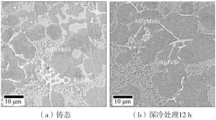
(a) In a cast state (b) Cryogenic treatment for 12 hours
Figure 6 Microstructure morphology of iron-containing phase of die-cast aluminum-silicon alloy in a cast state and cryogenically cooled for 12 hours
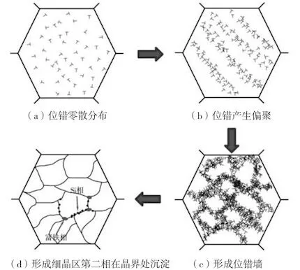
(a) Scattered distribution of dislocations (b) Dislocations produce segregation
(d) The second phase in the fine-grained area is formed and precipitates at the grain boundary.
(c) Formation of dislocation walls
Figure 7 The schematic diagram of grain changes during cryogenic cooling
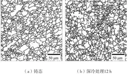
(a) In a cast state (b) Cryogenic treatment for 12 hours
Figure 8 The schematic diagram of EBSD grain size in a cast state and after cryogenic cooling for 12 hours.
Figure 3 shows the mechanical properties of die-cast aluminum-silicon alloys subjected to different cryogenic treatments. When cast, the alloy has a tensile strength of 184.8MPa, elongation 6.35%, and hardness HV 90.3. Cryogenic treatment can effectively improve the mechanical properties of die-cast aluminum-silicon alloys. After cryogenic treatment for different times, the mechanical properties of the alloy first increase and then decrease. When the cryogenic treatment time is 12 hours, the mechanical properties of the alloy are maximized, with a tensile strength of 213.2MPa, elongation 8.65%, and hardness HV106.6. Compared with the properties of the as-cast alloy, the tensile strength increased by 15.4%, elongation 36.2%, and hardness 18.1%. By continuing to extend the cryogenic treatment time, although the improvement in the mechanical properties of the alloy gradually decreases, it is still higher than the mechanical properties of the cast aluminum-silicon alloy. When the cryogenic treatment time is 48 hours, the tensile strength of the alloy is 200.6MPa, elongation 7.5%, and hardness HV97.4, which is already lower than the mechanical properties of the alloy after cryogenic treatment for 6 hours. From the perspective of energy conservation, environmental protection and production efficiency, it is of little significance to continue to increase the cryogenic treatment time to improve the mechanical properties of die-cast aluminum-silicon alloys.
Figure 3 Mechanical properties of die-cast aluminum-silicon alloys treated by different cryogenic treatment processes
2.2 Effect of cryogenic treatment on α-Al phase
Figure 4 shows the morphology of the α-Al phase of die-cast aluminum-silicon alloy treated by different cryogenic treatment processes. For the as-cast die-cast aluminum-silicon alloy, as shown in Figure 4a, the α-Al phase is relatively coarse and has more columnar crystals. The average particle size measured using Image-Pro Plus analysis was 27.22μm. Figure 4b shows the structure after cryogenic treatment for 6 hours. The α-Al phase has been refined and the coarse columnar crystals have been reduced. However, there is still some agglomeration, and the average particle size is 24.42μm. As the cryogenic time increases, the α-Al phase is further refined. When the cryogenic time is 12 hours, the α-Al phase is the smallest, with an average particle size of 22.41μm. Continuing to increase the cryogenic time, the average particle size of α-Al phase increases slightly, but its size is still lower than that of the as-cast alloy compared with the cryogenic sample treated for 12 hours. In short, cryogenic treatment can refine the grains, reduce the agglomeration of columnar crystals and α-Al phases, and promote a more uniform distribution of the organizational structure.
(a) The cast state (b) Cryogenic treatment for 6 hours (c) Cryogenic treatment for 12 hours
(d) Cryogenic treatment for 24 hours (e) Cryogenic treatment for 48 hours (f) Average particle sizes of a-Al phase
Figure 4 Microstructure morphology of α-Al phase of die-cast aluminum-silicon alloy treated by different cryogenic treatment processes
2.3 Effect of cryogenic treatment on eutectic Si phase
Figure 5 shows the morphology of the eutectic Si phase of die-cast aluminum-silicon alloy treated by different cryogenic treatment processes. The eutectic Si phase of the cast alloy is mostly in the form of flakes or strips, as shown in Figure 5a. After cryogenic treatment, the eutectic Si phase begins to become shorter and finer, transforming into a granular form. When the cryogenic time is 12 hours, the eutectic Si phase is significantly refined and tends to be round, as shown by the arrow in Figure 5c. Continuing to increase the cryogenic time, the eutectic Si phase begins to grow slowly again, as shown in Figure 5d and e.
(a) In a cast state (b) Cryogenic treatment for 6 hours (c) Cryogenic treatment for 12 hours
(d) Cryogenic treatment for 24 hours (e) Cryogenic treatment for 48 hours
Figure 5 Microstructure of eutectic Si phase of die-cast aluminum-silicon alloy treated by different cryogenic treatment processes
2.4 Effect of cryogenic treatment on iron-containing phase
Figure 6 shows the morphology of the iron-containing phase of die-cast aluminum-silicon alloy in the as-cast state and cryogenically cooled for 12 hours. The as-cast alloy contains a polygonal block AlFeMnSi phase and a long needle-shaped Al5FeSi phase, as shown in Figure 6a. After cryogenic treatment, the Al5FeSi phase shrinks and becomes passivated, and its outline becomes smooth. The sharp-edged AlFeMnSi phase also tends to be rounded, as shown by the arrow in Figure 6b. After cryogenic treatment, the size of the iron-containing phase in the die-cast aluminum-silicon alloy becomes smaller and its morphology changes, which greatly reduces the effect of splitting on the aluminum matrix.
3. Analysis and discussion
The volume of aluminum-silicon alloy shrinks treated by cryogenic treatment, which causes microscopic stress inside the material and promotes plastic deformation of the material. Figure 7 is a schematic diagram of the refinement process of the tissue produced by the cryogenic process. Before cryogenic treatment, dislocations in the alloy are scattered and have a low density, as shown in Figure 7a; at the beginning of cryogenic treatment, as shown in Figure 7b, the microscopic stress is small, and dislocations inside the grains will gather partially and form dislocations. As the cryogenic treatment proceeds, the stress accumulation increases, and the dislocations gather and become small-angle grain boundaries, which refines the grains, as shown in Figure 7c; the solubility of Si, Fe and other solute atoms in the alloy in the aluminum matrix decreases, and the solute atoms will segregate at dense dislocations near the grain boundaries. As the cryogenic time increases, Si phase and iron-rich phase precipitate at the grain boundaries, as shown in Figure 7d. These precipitated phases are smaller, more uniform and round, pinning the grain boundaries and hindering dislocation movement. The improvement of the mechanical properties of aluminum alloys has a significant effect. Figure 8 is a schematic diagram of the EBSD grain size distribution of the two samples in a cast state and cryogenically treated for 12 hours. Under cryogenic treatment, aluminum-silicon alloy does produce many fine-grained structures, as shown by the arrows in the figure. According to the Hall-Petch formula:

In the formula: σs is the yield strength of polycrystal; d is the average diameter of grains; σ0 is the resistance to deformation within the grain, which is equivalent to the yield strength of a single crystal; K is the influence coefficient of grain boundaries on deformation, which is related to the grain boundary structure. It can be seen that the smaller the grain size is, the greater the yield strength becomes, and it is difficult for dislocations to move. This is the main reason why the tensile strength and plasticity of the alloy are improved after cryogenic cooling for 12 hours.
(a) In a cast state (b) Cryogenic treatment for 12 hours
Figure 6 Microstructure morphology of iron-containing phase of die-cast aluminum-silicon alloy in a cast state and cryogenically cooled for 12 hours

(a) Scattered distribution of dislocations (b) Dislocations produce segregation
(d) The second phase in the fine-grained area is formed and precipitates at the grain boundary.
(c) Formation of dislocation walls
Figure 7 The schematic diagram of grain changes during cryogenic cooling

(a) In a cast state (b) Cryogenic treatment for 12 hours
Figure 8 The schematic diagram of EBSD grain size in a cast state and after cryogenic cooling for 12 hours.