Lightweight design for automotive chassis components focuses on utilizing advanced materials and optimizing structural designs. In this study, the front suspension arm of an automotive chassis is examined under two approaches: one involving the use of high-strength and ultra-high-strength steel, and the other utilizing a structural design with a double-piece buckle and a single-piece optimized structure. A mathematical simulation model is used to compare a high-strength steel double-piece buckle design with an ultra-high-strength steel single-piece structure. CAE analysis is performed to assess performance under L1 and L2 working conditions for the front suspension arm. The simulation results demonstrate that the ultra-high-strength steel single-piece design offers superior structural optimization compared to the high-strength steel double-piece buckle design, while also supporting thin-walled, hollow, and miniaturized components. The ultra-high-strength steel design achieves a 21% weight reduction over the high-strength steel design, offering significant advantages in lightweight design.
1. Introduction
Reducing a vehicle's curb weight while maintaining strength and safety improves performance, reduces fuel consumption, and lowers exhaust emissions. Studies show that a 100 kg reduction in vehicle weight can decrease fuel consumption by 0.4 L/100 km and CO₂ emissions by 10 g/100 km. As a result, weight reduction has become a global priority in automotive development. Automotive weight reduction combines design, material selection, and advanced manufacturing techniques. It is achieved through two main strategies: (1) The use of new materials involves incorporating lightweight materials and advanced molding technologies to reduce component weight. (2) Structural optimization focuses on designing thin-walled, hollow, miniaturized, or composite components while improving structural and manufacturing processes. Weight reduction through materials includes high-strength steel, magnesium alloys, aluminum alloys, engineering plastics, composites, and ceramics. This paper focuses on the design and application of high-strength steel in automotive chassis components, emphasizing material weight reduction and structural optimization to achieve overall weight savings.
2. Overview of the Application of Ultra-High Strength in Automotive Parts
As automotive material technology advances, the composition of materials used in modern vehicle manufacturing continues to evolve. Steel constitutes 55% to 60% of a car's total weight, cast iron accounts for 5% to 12%, non-ferrous metals 6% to 10%, plastics 8% to 12%, rubber 4%, glass 3%, and other materials, such as paint and liquids, make up 6% to 12%. Figure 1 shows the material distribution in automotive applications. Steel remains the dominant material in automotive manufacturing due to its high strength, plasticity, impact resistance, recyclability, and cost-effectiveness. High-strength steel in automotive chassis parts can reduce weight by approximately 30% compared to conventional steel, while aluminum alloys are about 30% less expensive.
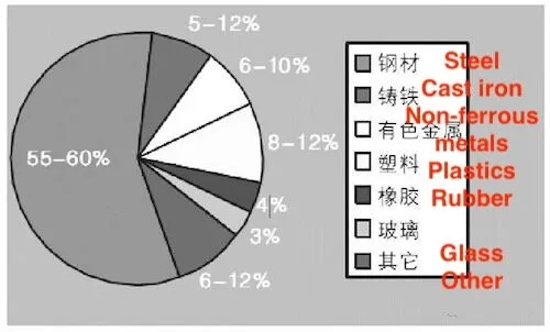
Figure 1 Ratio of automotive application materials
High-strength steel provides two key benefits in automotive applications: (1) The use of high-strength steel plates reduces body panel thickness and weight while improving safety performance. For example, reducing the thickness of a steel plate by 0.05 mm, 0.10 mm, and 0.15 mm reduces weight by 6%, 12%, and 18%, respectively. (2) High-strength steel typically includes cold-rolled steel with a yield strength of 340 MPa and hot-rolled steel with a yield strength of 490 MPa or higher. The uniform mechanical properties of high-strength steel plates enhance collision performance and extend fatigue life.
High-strength steel is broadly categorized into conventional high-strength steel (CHSS) and advanced high-strength steel (AHSS). Common advanced high-strength steels include complex-phase (CP) steel, dual-phase (DP) steel, transformation-induced plasticity (TRIP) steel, and twin-induced plasticity (TWIP) steel. Traditional high-strength steels are usually strengthened through solution treatment and grain refinement. Common traditional high-strength steels include high-strength IF steel (HSIF), bake-hardening (BH) steel, cold-rolled isotropic (IS) steel, cold-rolled high-strength P-containing steel, and high-strength low-alloy (HSLA) steel.
3. Application of Lightweight Design in Ultra-High-Strength Steel Chassis Components
Ultra-high-strength steel is commonly used in automotive chassis components. For example, the design of the front suspension swing arm, which functions under dynamic loads and high-stress conditions within the vehicle's suspension system, demonstrates its application. A CAE analysis of the swing arm design for a specific model was conducted, considering L1 and L2 working conditions as detailed in Tables 1 and 2.
Table 1: L1 working condition requirements for front suspension swing arm
|
L1 Working Condition |
Plastic Strain Requirement |
|
FX |
Maximum plastic strain is less than 1%. |
|
FY |
|
|
FZ |
|
|
MZ_LE |
|
|
MZ_TE |
|
|
nFZ |
Table 2: L2 Working Condition Requirements for Front Suspension Swing Arm
|
L2 Working Condition |
Maximum Stress (MPa) |
Requirement |
|
FX |
490 |
Maximum stress is less than the tensile strength of the material. |
|
FY |
462 |
|
|
FZ |
275 |
|
|
nFZ |
84 |
3. Structural Design of the Front Suspension Swing Arm
In the design of the front suspension swing arm, the component body is engineered to meet the L1 and L2 working conditions through the selection of materials and the application of structural design strategies. This section examines the design options for the front suspension swing arm body, utilizing high-strength and ultra-high-strength steel. The design concepts are summarized in Table 3.
Table 3 Design ideas for front suspension swing arm
|
Design Idea |
Main Material |
Structural Form |
|
Concept 1 |
High-strength steel |
Double-piece snap-fit type |
|
Concept 2 |
Ultra-high-strength steel |
Single-piece type |
3. Design Analysis for Concept 1: High-Strength Steel and Double-Piece Snap-Fit Structure
The design analysis for each of the two concepts is presented below:
(1) Concept 1: Several commonly used high-strength steels, including SAPH370, SAPH400, SAPH440, QStE360, QStE380, QStE420, and QStE460, are evaluated for use in the front suspension swing arm body. After evaluating factors such as performance, cost, manufacturability, and others, QStE460 material and a double-piece snap-fit structure are selected to meet the requirements based on CAE analysis. The CAE simulation results are shown below:
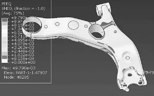
Figure 2: L1 level load Fx direction plastic strain cloud diagram
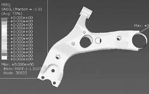
Figure 3: L1 level load Fy direction plastic strain cloud diagram
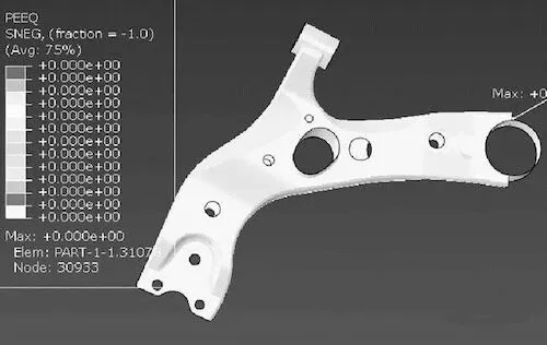
Figure 4: L1 level load Fz direction plastic strain cloud diagram
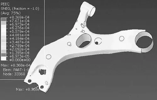
Figure 5: L1 level load MZ_LE direction plastic strain cloud diagram
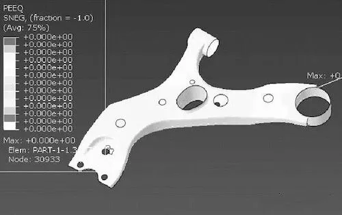
Figure 6: L1 level load MZ_TE direction plastic strain cloud diagram
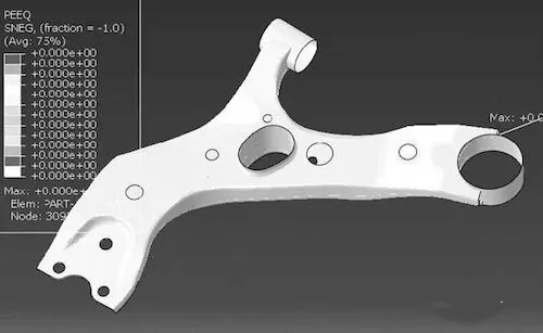
Figure 7: L1 level load nFZ direction plastic strain cloud diagram
The CAE simulation analyzes the front suspension swing arm under L1 working conditions. The maximum plastic deformation values in the Fx, Fy, Fz, MZ_LE, MZ_TE, and nFZ directions are compared with the allowable plastic strain for L1 working conditions. The analysis results are presented in Table 4.
Table 4 Plastic strain analysis results of L1 level working condition
|
Component |
Plastic Strain Requirements |
Maximum Plastic Strain |
Does It Meet the Requirements? |
|
Fx |
Plastic strain < 1% |
0.98% |
Yes |
|
Fy |
Plastic strain < 1% |
0.0% |
Yes |
|
Fz |
Plastic strain < 1% |
0.0% |
Yes |
|
MZ_LE |
Plastic strain < 1% |
0.19% |
Yes |
|
MZ_TE |
Plastic strain < 1% |
0.0% |
Yes |
|
nFZ |
Plastic strain < 1% |
0.0% |
Yes |
The analysis for L2 working conditions is presented below:
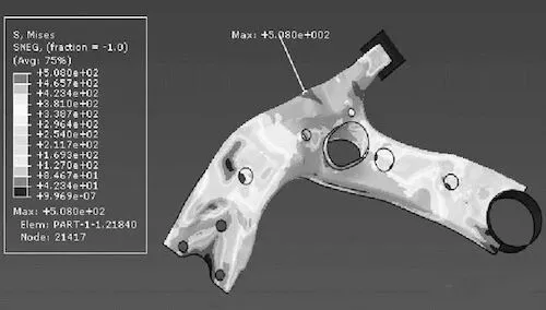
Figure 8: L2 level load Fx direction stress cloud diagram
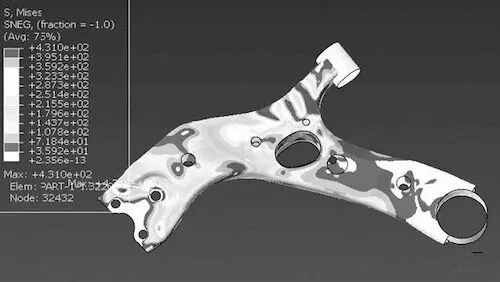
Figure 9: L2 level load Fy direction stress cloud diagram
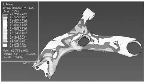
Figure 10: L2 level load Fz direction stress cloud diagram
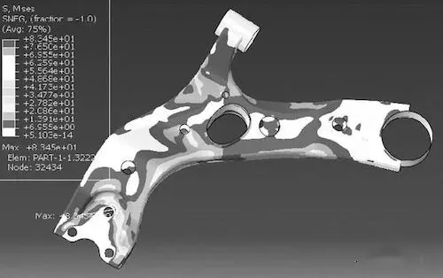
Figure 11: L2 level load nFZ stress cloud diagram
The CAE simulation analyzes the front suspension swing arm under L2 working conditions. The maximum stress values in the Fx, Fy, Fz, and nFZ directions are compared to the specified stress requirements. The analysis results are presented in Table 5.
Table 5 L2 level working condition stress analysis results
|
Component |
Stress Requirements |
Maximum Stress |
Does It Meet the Requirements? |
|
Fx |
Maximum stress < Tensile strength (QStE460 tensile strength 520-670 MPa) |
478 MPa |
Yes |
|
Fy |
Maximum stress < Tensile strength (QStE460 tensile strength 520-670 MPa) |
431 MPa |
Yes |
|
Fz |
Maximum stress < Tensile strength (QStE460 tensile strength 520-670 MPa) |
275 MPa |
Yes |
|
nFZ |
Maximum stress < Tensile strength (QStE460 tensile strength 520-670 MPa) |
83 MPa |
Yes |
The front suspension swing arm body is constructed using QStE460 and a double-piece snap-fit structure to satisfy the L1 and L2 working conditions. The structural diagram and design weight are presented in Table 6.
Table 6 Application of high-strength steel in a front suspension swing arm
|
Main Material Name |
Structural Form |
Structural Diagram |
Required Weight |
Design Weight |
|
QStE460 |
Double-piece type |
|
≤3.864Kg |
3.852Kg |
(2) Concept 2: Application of Ultra-High-Strength Steel in the Front Suspension Swing Arm
The front suspension swing arm is constructed from ultra-high-strength steels, including SAPH590, SAPH780, SAPH440, QStE550, QStE600, and 780HB, as its primary materials. After evaluating factors such as performance, cost, manufacturability, and other considerations, 780HB material and a single-piece structure are selected. CAE analysis confirms that the design meets the requirements.
Analysis of the double-piece structure reveals that risk conditions occur in the Fx and Fy directions under both L1 and L2 conditions. The simulation results for these conditions are presented below. The L1 level condition analysis is as follows:
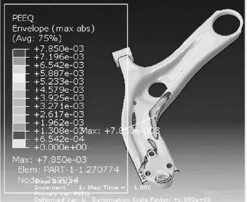
Figure 12: Plastic strain cloud diagram of L1 level load in the Fx direction
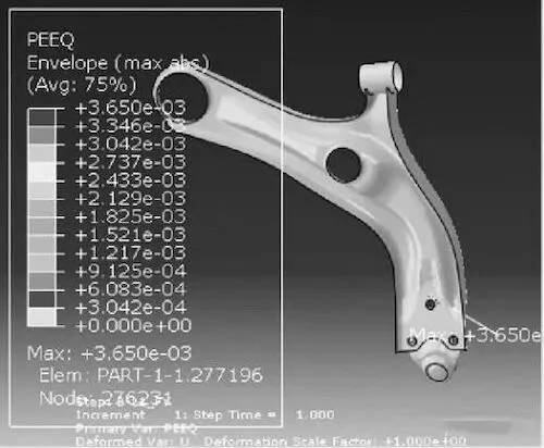
Figure 13: Plastic strain cloud diagram of L1 level load in the Fy direction
According to the CAE simulation, the maximum plastic deformation of the front suspension swing arm in the risk directions (Fx and Fy) under L1 level conditions was compared with the plastic strain requirements. The analysis results are provided in Table 7.
Table 7 Plastic strain analysis results of L1 working condition
|
L1 Working Load |
Fx |
Fy |
Plastic Strain Requirement |
Plastic Strain Maximum Value |
Does it Meet the Requirements? |
|
|
0.79% |
0.37% |
Plastic strain maximum less than 1% |
0.79% / 0.37% |
Yes |
L2 Working Condition Analysis
The analysis under L2 working conditions is presented below:
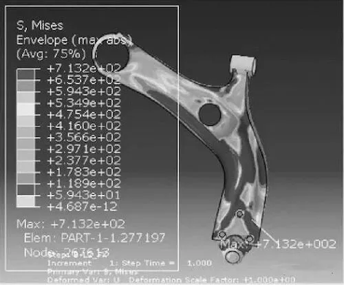
Figure 14: Stress distribution diagram of L2 load in the Fx direction
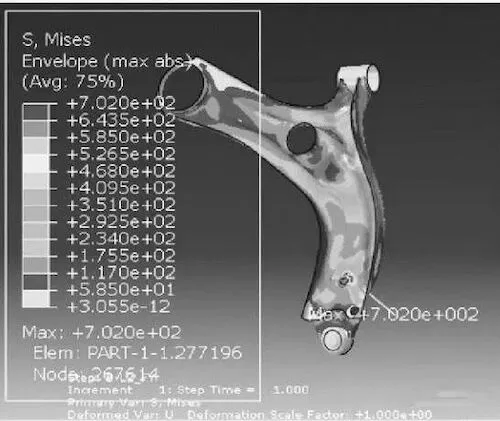
Figure 15: Stress distribution diagram of L2 load in the Fy direction
CAE analysis of the front suspension swing arm under L2 working conditions shows that the maximum stress values in the Fx and Fy directions were compared with the specified stress limits. The results of the analysis are presented in Table 8.
Table 8 Stress analysis results of L2 working conditions
|
L2 Working Load |
Fx |
Fy |
|
Stress Requirements |
The maximum stress is less than the tensile strength (Tensile strength ≥ 780 MPa). |
|
|
Maximum Stress |
713 MPa |
702 MPa |
|
Does it Meet the Requirements? |
Yes |
Yes |
The front suspension swing arm body is manufactured from 780HB with a monolithic structure. The structural diagram and design weight, compliant with L1 and L2 working conditions, are presented in Table 9.
Table 9: Application of ultra-high strength steel in a front suspension swing arm
|
Main Material Name |
Structural Form |
Structural Diagram |
Required Weight |
Design Weight |
|
780HB |
Single-piece type |
|
≤3.864 Kg |
3.178 Kg |
4. Analysis of CAE Simulation Results
The front swing arm of a vehicle model was designed and analyzed using both high-strength steel and ultra-high-strength steel, under identical working conditions and weight requirements. The analysis yielded the following results:
- The design, utilizing high-strength steel QStE460 and ultra-high-strength steel 780HB, successfully met the requirements for L1 and L2 working conditions.
- Designs incorporating high-strength steel require both upper and lower plates, with additional reinforcements in areas with stress concentrations or significant plastic deformation. In contrast, designs using ultra-high-strength steel adopt a monolithic structure, where only the shape in stress-concentrated areas or areas prone to plastic deformation needs modification to enhance strength.
- The front suspension swing arm made from ultra-high-strength steel is approximately 21.2% lighter than its high-strength steel counterpart, significantly contributing to the overall lightweight design of the chassis.
5. Conclusion
- Under identical working conditions, both ultra-high-strength steel and high-strength steel enable the design of the front suspension swing arm. These materials improve the performance of thin-walled, hollow, miniaturized, and composite structures, as well as enhance manufacturing efficiency.
- The design weight of components made from ultra-high-strength steel can be reduced by 21.2% compared to those made from high-strength steel, offering a lightweight solution for chassis components through optimized design.
- Ultra-high-strength steel has lower elongation than high-strength steel, which makes components with deep drawing requirements more prone to cracking and other defects during stamping. Thus, prioritizing stamping CAE analysis during the early design stages is crucial when using ultra-high-strength steel.