Aluminum alloys are lightweight, high-strength, and easily recyclable, making them widely used in the automotive industry. With the rapid growth of new energy vehicles, priorities such as integration, lightweight design, and high efficiency have become central to design and manufacturing. Some of the most common applications include large integrated castings, such as the front cabin, rear floor, and battery box. Heat treatment of large castings often leads to significant thermal deformation and high scrap rates. To address these challenges, various heat-treatment-free die-casting aluminum alloys have been developed both domestically and internationally, primarily in the AlSi and AlMg series. The AlMg series offers superior strength and toughness, but its casting performance is inferior to that of the AlSi series. As a result, AlSi-series alloys, known for their excellent fluidity and complete filling, are predominantly used in current large integrated castings. The C611 alloy, developed by Alcoa, and Castasil 37, developed by RHEIN-FELDEN in Germany, are two representative heat-treatment-free AlSi alloys. A systematic comparative analysis of the structure and performance of these materials provides a deeper understanding of their development principles and characteristics, offering valuable insights into composition and process optimization for practical applications.
1. Experimental Materials and Methods
1.1 Materials
The theoretical composition for the two alloys are presented in Table 1.
Table 1 The chemical composition of alloy
|
Alloy |
Si |
Fe |
Cu |
Mn |
Mg |
Zn |
Ti |
Sr |
Others |
|
C611 |
6.0–9.0 |
0.15 |
- |
0.4–0.8 |
0.15–0.30 |
- |
0.1 |
0.01–0.03 |
- |
|
Castasil 37 |
8.5–10.5 |
0.15 |
0.05 |
0.35–0.6 |
0.06 |
0.07 |
- |
0.01–0.015 |
Mo, Zr |
1.2 Testing Methodology
The compositions of the two alloy ingots were analyzed using a Bruker Q4 TASMAN direct-reading spectrometer. Based on the measured compositions, solidification curves for both alloys were calculated using Pandat software. The die-casting tests were performed using a TOYO BD 350 V5-EX die-casting machine. Sample preparation followed the GB/228.1-2010 standard, and the dimensions of the tensile specimens are shown in Figures 1a and 1b. Additionally, tensile specimens were wire-cut from mass-produced vacuum die-casting battery boxes, which feature a characteristic wall thickness of 3 mm, as shown in Figure 1c. Mechanical properties were tested using a Shimadzu AGX-100 kN universal testing machine. After grinding and polishing, the samples were exposed to a 0.5% HF solution for 1-3 seconds to facilitate observation of the metallographic structure under a Leica DM6M metallographic microscope. The distribution of the precipitated phase was examined using a Zeiss Sigma 300 scanning electron microscope (SEM) and an Oxford Xplore30 energy-dispersive X-ray spectroscopy (EDS) system to determine the phase composition. Differential scanning calorimetry (DSC) was conducted on wire-cut samples using a Mettler Toledo DSC3 differential scanning calorimeter, with temperature ranges of 25-700 °C and 700-400 °C, heating and cooling rates set to 10 K/min. The thermal diffusivity was measured using a Netzsch LFA467 laser flash apparatus, within the temperature range of 25–300°C. Specific heat capacity was also tested using the Mettler Toledo DSC3, and thermal conductivity was calculated based on the obtained data.
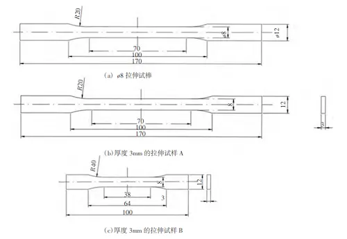
(a) The tensile test specimen with a thickness of 8 mm (b) The tensile specimen A with a thickness of 3 mm
(c) The tensile specimen B with a thickness of 3 mm
Figure 1 Dimensions of tensile specimen
2. Results and Analysis
2.1 Composition and Solidification Simulation
The compositions of the alloys, presented in Table 2, were input into Pandat software for solidification simulation, with the results shown in Figure 2. The simulated solidification curves indicate that Castasil 37 enters the eutectic solidification stage earlier than C611 and has a narrower solidification temperature range. This difference is primarily due to the higher Si content in Castasil 37. In hypoeutectic Al-Si alloys, higher silicon content narrows the solidification temperature range, boosts the latent heat of solidification, and enhances fluidity. However, during actual production, Castasil 37 is more prone to cold shut during die casting. To prevent these, the aluminum melt temperature in the holding furnace must be maintained above 750°C. In contrast, C611 achieves full mold filling at 730°C without cold shut. This suggests that while a narrower solidification temperature range reduces the risk of hot cracking, it also increases the likelihood of cold shut due to the shorter solidification time within the mold cavity.
2.2 Comparison of DSC Results
The DSC heating test results are shown in Figure 3. Both alloys exhibit two endothermic peaks. The first peak corresponds to the melting of the eutectic phase, and the second peak represents the melting of the α (Al) phase. The Si content of Castasil 37 is closer to the eutectic point than that of C611, leading to a less distinct separation between the two peaks compared to C611. The solidus temperature is defined as the starting temperature of the eutectic phase melting endothermic peak, marking the transition to the liquid phase.
Table 2 Measured composition of alloys
|
Alloy |
Si |
Fe |
Cu |
Mn |
Mg |
Zn |
Ti |
Sr |
Mo |
Zr |
|
C611 |
7.378 |
0.102 |
0.06 |
0.534 |
0.231 |
0.008 |
0.063 |
0.021 |
- |
- |
|
Castasil 37 |
10.16 |
0.103 |
0.004 |
0.403 |
0.009 |
0.008 |
0.078 |
0.015 |
0.024 |
0.09 |
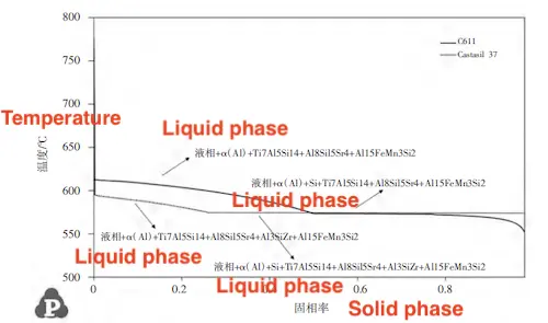
Figure 2 Curve of alloy solidification solid phase rate changing with temperature
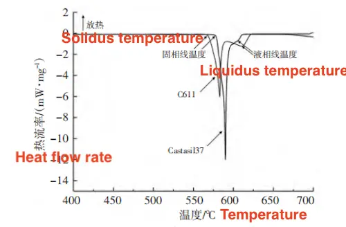
Figure 3 Comparison of DSC heating curves of two alloys
The phase line temperature refers to the peak temperature of the endothermic melting peak of the α (Al) phase. As shown in Table 3, the solidification temperature range for Castasil 37 is narrower than that of C611, consistent with the results from the solidification simulation. The DSC cooling test results are shown in Figure 4. Both alloys exhibit two exothermic peaks in their cooling solidification curves. The first exothermic peak corresponds to the solidification of the α (Al) phase, while the second corresponds to the solidification of the eutectic phase. The starting temperature of the α (Al) phase solidification peak marks the solidification start temperature. As shown in Table 3, the solidification start temperature for C611 is higher than that of Castasil 37, which agrees with the solidification simulation results.
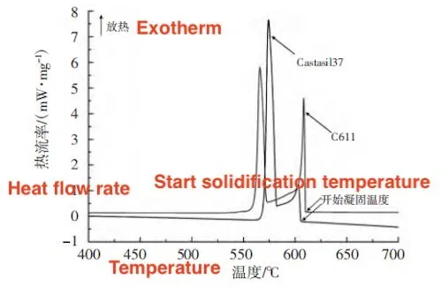
Figure 4: Comparison of DSC Cooling Curves for the Two Alloys
2.3 Microstructure and Precipitation Phase Observation
Both C611 and Castasil 37 are hypoeutectic alloys. During solidification, the primary α (Al) phase forms first, followed by the precipitation of the Si phase during eutectic formation. The eutectic (Al plus Si) structure is located at the grain boundaries of the α (Al) matrix, with precipitates predominantly distributed within this structure. As shown in Figure 5, the microstructures of both alloys are similar, consisting mainly of α (Al), an aluminum-silicon eutectic structure, and precipitates. Castasil 37, with its higher Si content, has a larger amount of eutectic silicon structure. Both alloys contain Sr, and the effects of eutectic structure modification are similar in both cases. Notably, Castasil 37 shows more uniform edge structure distribution compared to C611. Composition analysis reveals that the addition of Mo and Zr in Castasil 37 promotes the formation of fine, dispersed strengthening phases during solidification, inhibiting the growth of α (Al).
Using the backscattering (BSD) probe of the SEM, the precipitate phases are distinguishable from the matrix, which contains Al and Si, due to elements like Mn and Fe. As shown in Figure 6, the precipitates in C611 are polygonal and distributed within the eutectic structure. The energy spectrum results (Table 4, Spectrum 1) show that these precipitates are mainly composed of Fe, Mn, Al, and Si. Based on the literature, these precipitates are identified as α-Al15(MnFe)3Si2, which forms from the needle-like phase β-Al5FeSi. With the addition of Mn, some Fe atoms are replaced by Mn. Additionally, the energy spectrum shows the presence of Mg and Cu near some α-Al15(MnFe)3Si2 phases. These precipitates are identified as the Q-Al5Cu2Mg8Si6 phase (Table 4, Spectrum 2).
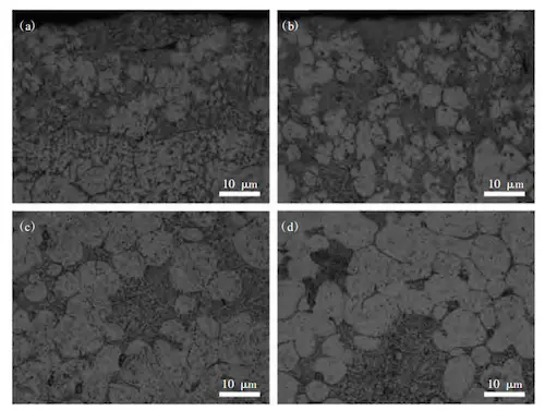
(a) Edge of C611 sample (b) Edge of Castasil 37 sample
(c) Core of C611 sample (d) Core of Castasil 37 sample
Figure 5: Microstructure of Alloys
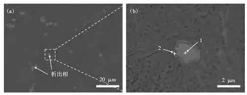
(a) Distribution of precipitate phase in eutectic structure (b) Morphology of precipitate phase
Figure 6: SEM Image of Precipitation Phase in C611 Alloy
Table 4 EDS analysis of precipitation phase of C611 alloy
|
Spectrum |
Al (%) |
Si (%) |
Mn (%) |
Fe (%) |
Mg (%) |
Cu (%) |
C (%) |
|
1 |
53.52 |
9.66 |
27.88 |
5.77 |
- |
- |
3.17 |
|
2 |
68.38 |
8.91 |
- |
- |
8.77 |
4.76 |
9.18 |
The precipitation phase in Castasil 37, shown in Figure 7, is similar to that in C611, distributed within the eutectic structure between the grains. In addition to polygonal particles, Castasil 37 also contains lath- and star-shaped precipitates. The edges of the polygonal particles in Castasil 37 are smoother than those in C611. As shown in Spectrum 1 of Table 5, these polygonal particles consist of Fe, Mn, Al, Si, and Mo. Literature suggests that Mo is likely incorporated into the α-Al15(MnFe)3Si2 phase, transforming it into a multi-phase granular structure composed of Al-Si-Mn-Fe-Mo. The spectra for the lath- and star-shaped precipitates, shown in Spectra 2 and 3 of Table 5, suggest these phases are Zr-based. Zr tends to aggregate before the α (Al) phase fully solidifies, forming (Al, Si)₃Zr phases, which restrict the growth of α (Al).

(a) Distribution of precipitation phase in eutectic structure (b) (c) Morphology of precipitation phase
Figure 7: SEM Images of Castasil 37 Alloy Precipitation Phase
Table 5 EDS analysis of Castasil 37 alloy precipitation phase
|
Spectrum |
Al (%) |
Si (%) |
Mn (%) |
Fe (%) |
Mo (%) |
Zr (%) |
C (%) |
|
1 |
46.91 |
9.8 |
20.18 |
5.43 |
11.60 |
- |
2.98 |
|
2 |
56.77 |
11.50 |
- |
- |
- |
28.69 |
3.03 |
|
3 |
47.45 |
12.68 |
- |
- |
- |
39.86 |
- |
The distribution of the precipitated phases at both the edge and core positions of the alloys was observed and compared. As shown in Figure 8, the precipitate size in the core of both alloys is comparable. However, the precipitated phase at the edge of Castasil 37 is finer and more uniformly distributed than that of C611. This is due to the rapid cooling conditions typical of thin-walled castings, where Castasil 37’s finer precipitate structure enhances precipitation strengthening, making it better suited for such applications.
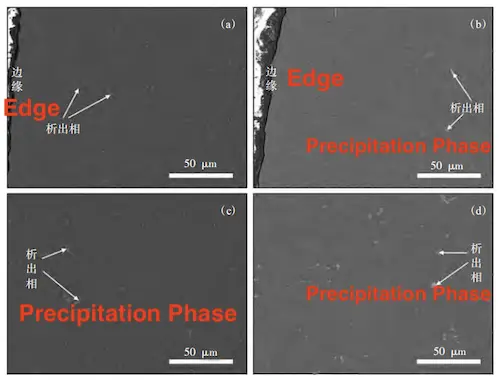
(a) Edge position of C611 alloy (b) Edge position of Castasil 37 alloy
(c) Core position of C611 alloy (d) Core position of Castasil 37 alloy
Figure 8: SEM Images of Alloys
2.4 Comparison of Mechanical Properties
The mechanical properties of the alloys are summarized in Table 6. Under non-vacuum conditions, C611 exhibits slightly higher tensile strength, yield strength, and elongation than Castasil 37. However, for the flat sample, Castasil 37 shows approximately 6% higher tensile and yield strengths than C611, indicating its superior performance in filling thin-walled parts. The elongation of both alloys under non-vacuum conditions is approximately 5%, which is significantly lower than the alloys' typical values, likely due to insufficient exhaust and slag removal in the flat sample cavity. This led to excessive pores, resulting in a considerable reduction in elongation. Furthermore, this suggests that both alloys require vacuum die-casting for optimal performance in thin-walled parts. In vacuum die-casting tests with body samples, both alloys exhibited elongation values exceeding 11%, with C611 reaching 13.6%, while Castasil 37 demonstrated the highest yield strength at 135 MPa. Overall, C611's mechanical properties show little sensitivity to changes in wall thickness or vacuum conditions, with superior elongation performance. Castasil 37, on the other hand, is better suited for die-casting thin-walled parts under vacuum conditions, offering superior tensile and yield strengths.
Table 6: Comparison of Mechanical Properties of Two Alloys Under Different Conditions
|
Alloy |
Process |
Sample Shape |
Size (mm) |
Tensile Strength (MPa) |
Yield Strength (MPa) |
Elongation (%) |
|
C611 |
Non-vacuum |
Round rod |
Diameter: 8 |
271 |
110 |
13.0 |
|
C611 |
Non-vacuum |
Flat plate |
Thickness: 3 |
251 |
115 |
5.2 |
|
C611 |
Vacuum |
Flat plate |
Thickness: 3 |
258 |
117 |
13.6 |
|
Castasil 37 |
Non-vacuum |
Round rod |
Diameter: 8 |
270 |
108 |
10.0 |
|
Castasil 37 |
Non-vacuum |
Flat plate |
Thickness: 3 |
276 |
121 |
5.3 |
|
Castasil 37 |
Vacuum |
Flat plate |
Thickness: 3 |
266 |
135 |
11.7 |
2.5 Comparison of Thermal Conductivity
The thermal conductivity of the alloys was calculated using the formula λ = αρCp, where α, ρ, and Cp represent the measured values. Table 7 compares the thermal conductivity of the two alloys within the temperature range of 25–300°C. The thermal diffusivity and density of C611 are slightly higher than those of Castasil 37, while its specific heat is marginally lower. The calculated thermal conductivities of both alloys are comparable. At room temperature of 25°C, the thermal conductivity of both alloys is 127.1 W/m·K. As the temperature increases, the thermal conductivity also increases. At 300°C, the thermal conductivity of C611 reaches 180.7 W/(m·K), slightly higher than Castasil 37’s 173.2 W/(m·K).
The thermal conductivity of aluminum alloys is primarily influenced by the movement of free electrons, although phonon scattering also plays a significant role. When the temperature gradient remains constant, a more perfect crystal structure leads to a longer mean free path for electrons and higher thermal conductivity. The solid solubility of elements in aluminum alloys can cause greater lattice distortion, introduce more intergranular second phases, and increase electron scattering, resulting in a shorter mean free path and lower thermal conductivity. Castasil 37, with a higher Si content than C611, contains more eutectic precipitation phases between the α (Al) crystals. The addition of Cr and Mo results in precipitates in the cast state, reducing thermal diffusivity. However, the increased proportion of the (Al plus Si) eutectic structure raises the specific heat, balancing the overall thermal conductivity of the two alloys. As the temperature increases, the thermal motion of electrons accelerates, leading to more collisions with the lattice and a decrease in thermal conductivity. Additionally, as a heat-treatment-free alloy, the alloy elements dissolved in the α (Al) matrix precipitate more rapidly at higher temperatures, reducing lattice distortion and increasing the mean free path, thereby enhancing thermal conductivity.
Table 7 Comparison of thermal conductivity of two alloys
|
Alloy |
Temperature (°C) |
Thermal Diffusivity (mm²/s) |
Specific Heat (J/g·K) |
Thermal Conductivity (W/m·K) |
|
C611 |
25 |
58.7 |
0.802 |
127.1 |
|
C611 |
100 |
59.5 |
0.874 |
140.4 |
|
C611 |
200 |
61.4 |
0.940 |
155.8 |
|
C611 |
300 |
64.0 |
1.046 |
180.7 |
|
Castasil 37 |
25 |
56.9 |
0.834 |
127.1 |
|
Castasil 37 |
100 |
57.8 |
0.899 |
139.2 |
|
Castasil 37 |
200 |
58.2 |
0.971 |
151.4 |
|
Castasil 37 |
300 |
60.1 |
1.075 |
173.2 |
3. Conclusion
- Castasil 37 has a narrower solidification temperature range than C611, providing better thermal crack resistance. However, it requires a molten aluminum temperature above 750°C to prevent cold shut, while C611 can effectively fill the mold at a lower temperature of 730°C.
- Castasil 37 exhibits finer and more uniformly distributed precipitates under thin-wall conditions, which enhances its mechanical properties. The use of vacuum die casting significantly improves its elongation. In contrast, the mechanical properties of C611 remain largely unaffected by changes in wall thickness or vacuum conditions, although its elongation remains superior.
- The thermal conductivity of both alloys is identical at room temperature (127.1 W/(m·K)). As the temperature increases, the precipitation of solid solution alloying elements enhances the thermal conductivity. At 300°C, the thermal conductivity of C611 reaches 180.7 W/(m·K), slightly higher than Castasil 37’s 173.2 W/(m·K).